| Precision CNC Machining Fundamentals |
| Definition |
Computer Numerical Control machining |
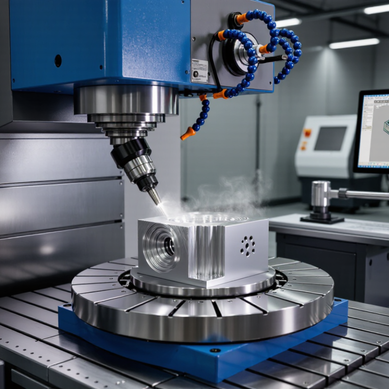
Material is removed according to programmed tool paths generated from digital design data. |
A controller converts numerical instructions into coordinated movement of cutting tools and workholding equipment. |
Supports repeatable production of complex parts with controlled dimensions and geometric features. |
| Primary operations |
Three-axis and multi-axis machining |
Common operations include milling, turning, drilling, boring, tapping, reaming and surface finishing. |
Rotating tools or workpieces remove material from metals, plastics and other machinable materials. |
The selected operation depends on the part geometry, material, tolerance and production volume. |
| Coordinate system |
Machine axes |
X, Y and Z axes are standard; additional rotary axes may be used for multi-sided or contoured parts. |
The machine positions the tool and workpiece relative to a defined work coordinate system. |
Accurate coordinate control reduces repositioning errors and improves access to complex features. |
| Design input |
CAD and CAM data |
Typical inputs include 2D drawings, 3D CAD models, material specifications and tolerance requirements. |
CAM software calculates tool paths, cutting motions, feeds, speeds and machining sequences. |
Complete design data helps prevent ambiguity during programming and inspection. |
| Material removal |
Cutting parameters |
Feed rate, spindle speed, depth of cut and tool engagement are selected according to material and tool type. |
A cutting tool shears chips from the workpiece while coolant or air may control heat and chip evacuation. |
Balanced parameters improve dimensional stability, tool life and surface quality. |
| Typical Precision and Surface Characteristics |
| Dimensional tolerance |
General machined features |
Approximately ±0.05 mm is commonly achievable under suitable process conditions; tighter values require controlled processes and verification. |
Accuracy depends on machine condition, tooling, thermal behavior, workholding, material and inspection method. |
Tolerance should be specified according to function because unnecessarily tight tolerances increase cost and inspection effort. |
| Fine tolerance capability |
Critical features |
Approximately ±0.01 mm may be achievable for selected features with specialized tooling, stable equipment and controlled inspection. |
Machining strategy, temperature control, tool compensation and multiple finishing passes are used to reduce variation. |
Suitable for interfaces, bores, locating features and components requiring controlled fit. |
| Surface roughness |
Machined surface finish |
Typical CNC milling or turning may produce about Ra 1.6–6.3 µm; fine finishing can achieve lower Ra values. |
Surface texture is influenced by tool geometry, feed rate, cutting speed, material and finishing passes. |
Surface finish affects friction, sealing, appearance, wear and fatigue performance. |
| Geometric control |
Flatness, parallelism and concentricity |
Controlled according to the engineering drawing and applicable geometric dimensioning and tolerancing requirements. |
Machine calibration, datum strategy, workholding and inspection alignment are used to control feature relationships. |
Geometric accuracy is often more important than a single linear dimension for assembly performance. |
| Common Applications |
| Aerospace components |
Structural fittings, brackets and housings |
Often manufactured from aluminum alloys, titanium alloys, stainless steels and high-strength nickel alloys. |
Multi-axis milling and controlled drilling create lightweight, contoured and accurately located features. |
Used where low weight, dimensional control, traceability and repeatability are important. |
| Automotive components |
Prototype parts, transmission elements and fixtures |
Common materials include aluminum, steel, stainless steel and engineering plastics. |
Turning and milling produce shafts, mounting features, housings, molds and production tooling. |
Supports rapid development, replacement parts and repeatable production components. |
| Medical devices |
Instrument components, implants and surgical tooling |
Materials may include titanium, stainless steel, cobalt-chromium alloys and medical-grade polymers. |
Small tools and controlled machining processes produce intricate forms and precise interfaces. |
Material control, cleanliness, documentation and inspection are critical for regulated products. |
| Industrial equipment |
Valve bodies, pump parts, gears and machine fixtures |
Materials are selected according to load, corrosion, temperature and wear requirements. |
Turning, boring, milling, drilling and tapping create functional mechanical interfaces. |
Accurate mating features help reduce leakage, vibration, premature wear and assembly problems. |
| Electronics and automation |
Enclosures, heat sinks, mounting plates and robotic parts |
Aluminum, copper, stainless steel and engineering plastics are frequently used. |
CNC machining creates mounting patterns, cable openings, thermal interfaces and lightweight structures. |
Useful for prototypes, low-volume production and customized equipment. |
| Energy equipment |
Flanges, connectors, impellers and structural components |
Material selection is based on pressure, temperature, corrosion and fatigue conditions. |
Precision boring, turning and multi-axis milling produce pressure and alignment features. |
Dimensional and material verification supports safe assembly and reliable operation. |
| Quality Checks in Precision CNC Manufacturing |
| Incoming material inspection |
Material grade and condition |
Checks may include certificates, dimensions, heat or lot identification and visual condition. |
Material information is compared with the drawing, purchase requirements and process plan. |
Prevents incorrect material from entering production and supports traceability. |
| First-article inspection |
Initial completed part |
Critical dimensions, tolerances, materials and required features are verified before regular production. |
The first part is measured against the engineering drawing or digital inspection plan. |
Confirms that programming, tooling, setup and process conditions are suitable. |
| In-process inspection |
Process monitoring |
Selected dimensions are checked during machining using probes, gauges or handheld instruments. |
Measurements identify tool wear, thermal drift, incorrect offsets or setup movement before completion. |
Reduces scrap and enables timely corrective action during production. |
| Dimensional inspection |
Calipers, micrometers and bore gauges |
Resolution and accuracy should be appropriate for the tolerance being evaluated. |
Contact instruments measure lengths, diameters, depths, steps and internal features. |
Provides fast verification of common dimensional requirements. |
| Coordinate measurement |
Coordinate Measuring Machine inspection |
Measures feature locations, sizes, form and relationships in three-dimensional space. |
A touch-trigger or scanning probe collects points and compares them with nominal CAD or drawing data. |
Suitable for complex geometries and tightly controlled geometric tolerances. |
| Surface inspection |
Roughness and visual evaluation |
Surface roughness may be reported using Ra, Rz or another specified parameter. |
A surface tester or approved visual standard evaluates texture, burrs, tool marks and damage. |
Confirms functional, sealing, sliding or cosmetic requirements. |
| Thread inspection |
Thread plugs, ring gauges or optical measurement |
Checks include thread size, pitch, effective diameter, depth and form. |
Gauges or measurement equipment verify whether internal and external threads meet specification. |
Ensures reliable fastening and prevents assembly failures. |
| Visual and functional inspection |
Appearance, burrs and fit |
Parts are checked for burrs, scratches, dents, contamination, sharp edges and assembly fit. |
Inspectors compare the finished part with acceptance criteria and, where required, perform a fit or function test. |
Identifies defects that may not be revealed by dimensional measurement alone. |
| Calibration control |
Inspection equipment status |
Measuring instruments should have valid calibration records and suitable measurement capability. |
Equipment is calibrated or verified at defined intervals against recognized standards. |
Improves confidence that reported measurements are accurate and traceable. |
| Final documentation |
Inspection report and traceability |
Records may include part number, revision, measured values, material information and inspection date. |
Results are reviewed against drawing requirements and retained according to the quality procedure. |
Provides evidence of conformity and supports repeatability, service and audit requirements. |
| Factors Affecting Machining Quality |
| Machine condition |
Accuracy, rigidity and thermal stability |
Wear, backlash, vibration and temperature changes can influence final dimensions. |
Preventive maintenance, calibration, warm-up routines and stable operating conditions reduce variation. |
Reliable equipment is essential for consistent precision machining. |
| Tool management |
Tool geometry and wear |
Tool material, coating, edge condition and remaining tool life affect cutting performance. |
Tool selection and replacement schedules are matched to the workpiece material and operation. |
Controls burr formation, dimensional drift, surface finish and production interruptions. |
| Workholding |
Fixture stability and datum location |
Clamping force must hold the part securely without causing excessive distortion. |
Fixtures establish repeatable datums and maintain part position throughout machining. |
Good workholding improves accuracy, accessibility and repeatability. |
| Process planning |
Operation sequence and setup strategy |
Machining order is selected to manage distortion, accessibility, stock removal and critical datums. |
Roughing, semi-finishing, finishing and inspection steps are arranged to control process variation. |
Effective planning reduces setup count, production time and rework risk. |