Choosing an Impulse Voltage Generator in 2026 requires more than comparing peak-voltage ratings. The right system must match your test objects, waveform requirements, laboratory space, and measurement capability. A generator designed for lightning impulses may perform poorly for switching impulses or repetitive testing. That difference matters.
In my experience, weak purchasing decisions often begin with one impressive number. A 1.2 MV label sounds powerful. It says little about waveform accuracy, load performance, erection time, or operator control. Ask how the generator behaves with real transformers, cables, insulators, and surge arresters. Examine front time, tail time, voltage efficiency, trigger stability, and energy per stage. Check whether the divider, oscilloscope, and software support traceable measurements. Calibration records matter.
Professor Klaus Schon, a respected high-voltage engineering specialist, expresses the central principle clearly: “A test result is only as reliable as the complete measuring system.” His observation should guide every specification review. The generator, measuring divider, connections, grounding network, and room layout work as one system.
Safety cannot remain an afterthought. Interlocked doors, discharge resistors, visible grounding points, emergency controls, and documented procedures deserve careful inspection. Verify applicable IEC and IEEE requirements with qualified engineers. Manufacturer claims still require independent scrutiny.
Some details are easy to overlook.
Noise, maintenance access, spare parts, and training influence daily reliability. A cheaper generator may create higher costs through downtime or repeated testing. Still, no selection guide removes uncertainty. Your laboratory may have unusual loads or limited space. Measure those realities before choosing. The best Impulse Voltage Generator is not always the largest; it is the most controllable, verifiable, and suitable for your actual testing program.
An impulse voltage generator creates brief, controlled surges for insulation testing. It imitates lightning strikes or switching events in electrical systems. The test reveals weak insulation, poor clearances, and unexpected flashover paths. In practice, a clean waveform matters as much as peak voltage. A distorted pulse can produce misleading results. Choose equipment that supports the required impulse shapes and measurement accuracy. IEC 60060-1 provides useful guidance for high-voltage testing methods.
Review the generator’s voltage range, energy capacity, repetition rate, and control system. Check whether it can test cables, transformers, switchgear, or other specific objects. A dry laboratory needs different arrangements from a production floor. Look for dependable voltage dividers, calibrated measurement channels, and clear fault records. Remote operation can reduce exposure during testing. Yet advanced software does not replace careful grounding and physical inspection. I have seen test plans fail because connection details were treated as minor.
Tips: Define the test object before selecting the generator. Confirm the required impulse type and tolerance. Ask for calibration evidence and service procedures. Inspect the grounding path every time. Leave space around the test area. A small gap can matter. Also, compare actual operating needs with impressive specifications. Higher voltage is not automatically better. If the waveform cannot be verified, the result deserves another review.
Choosing an impulse voltage generator in 2026 starts with the waveform, not the maximum voltage.
IEC 60060-1 defines the standard lightning impulse as 1.2/50 microseconds. Switching impulses commonly use 250/2500 microseconds. These figures change the generator’s capacitor, charging circuit, and measuring system.
Check the required peak voltage against the equipment’s insulation level. IEC 60071-1 connects insulation coordination with rated withstand voltages. A generator rated at 300 kV may still be unsuitable if its front time, tail time, or overshoot misses the test tolerance. IEEE Std 4-2013 also emphasizes validated measurement systems, not voltage readings alone. That detail is easy to underestimate.
Energy needs a separate calculation. Stored energy follows E = ½CV², so doubling voltage quadruples energy.
A 2 nF capacitor charged to 200 kV stores about 40 joules. Add losses, test-object capacitance, and repeated shots. The practical requirement becomes larger.
CIGRE Technical Brochure 549 highlights the importance of accurate impulse testing and insulation coordination in high-voltage systems. My early equipment choices focused too heavily on peak voltage. That was a mistake. A smaller generator with controlled wave-shaping can produce better evidence than a larger, poorly matched unit.
Ask for calibration records, waveform uncertainty, resistor replacement intervals, and real test-object examples before purchasing.
Numbers matter. So does test discipline.
Choosing an impulse voltage generator in 2026 requires more than comparing peak voltage. According to the International Energy Agency’s Electricity 2024 report, global electricity demand may grow by about 3.4% annually from 2024 to 2026. That growth increases testing pressure on transformers, cables, and insulation systems.
A multistage capacitor generator suits high-voltage laboratory work. A compact single-stage unit fits routine component tests. Marx configurations deliver steep fronts, but they need careful resistor coordination and grounding. For standard lightning impulses, verify the 1.2/50 μs waveform under IEC 60060-1. Switching-impulse testing needs different timing and energy settings. Do not select voltage alone. Stored energy, repetition rate, load capacitance, polarity change, and measurement bandwidth often determine practical performance. A manual control system can support simple, low-frequency tests. A PLC-based system improves sequencing and interlocks. Closed-loop control adds repeatability, though it cannot fix poor sensor placement or unstable grounding.
Tips: Ask for recorded waveform data, not only a specification sheet. Check overshoot, front time, tail time, and repeatability at your actual load. Confirm that the divider and digitizer share synchronized timing. Leave physical space for discharge resistors and maintenance access. I have seen technically correct systems fail during commissioning because the test room lacked a clean return path. That detail is easy to miss. A smaller generator may also be the wiser choice when testing frequency, floor space, and operator training matter more than maximum output. According to IEC 60060-1 practice, measurement uncertainty should be reviewed with the complete test circuit, not the generator alone.
| Evaluation Dimension | Single-Stage Capacitor-Discharge Generator | Conventional Marx Multistage Generator | Modular Marx Generator | Combined or Hybrid Impulse System | Recommended Selection Focus |
|---|---|---|---|---|---|
| Basic Operating Principle | A capacitor is charged to a defined voltage and discharged through a controlled spark gap or switching device. | Several capacitors are charged in parallel and connected in series during erection, producing a high-voltage impulse. | Preassembled impulse modules are combined in series or parallel to provide scalable voltage and energy. | Two or more impulse-generation methods are integrated, such as a Marx generator with a front-of-wave or chopping circuit. | Match the circuit topology to the required voltage, energy, waveform flexibility, repetition rate, and test-object capacitance. |
| Typical Laboratory Voltage Range | Up to approximately 100 kV Common for component, material, and educational testing. | Approximately 100 kV to several MV Common for high-voltage equipment and insulation testing. | Approximately 100 kV to several MV Range is determined by the number and rating of modules. | Approximately 100 kV to several MV Usually selected for specialized waveform or multi-purpose laboratories. | Specify both the maximum crest voltage and the required voltage tolerance at the test object, not only the nominal generator rating. |
| Energy Capability | Low to moderate stored energy; suitable when the test object has relatively low capacitance. | Moderate to high stored energy; energy increases with stage capacitance and charging voltage. | Scalable stored energy; individual modules can be sized for the required load and duty cycle. | Moderate to very high, depending on the primary generator and auxiliary circuits. | Calculate required energy using the generator and test-object capacitances, allowing for circuit losses and voltage efficiency. |
| Standard Lightning Impulse | Can be designed for the standard 1.2/50 μs lightning impulse waveform at suitable loads. | Widely used for 1.2/50 μs lightning impulse testing; wave-shaping resistors and inductors are normally required. | Can generate 1.2/50 μs waveforms with digitally controlled charging and configurable wave-shaping networks. | Can support standard and specialized lightning impulses, including chopped lightning impulses. | Confirm waveform parameters at the test object according to IEC 60060-1 or IEEE Std 4 measurement requirements. |
| Standard Switching Impulse | Generally less economical for long-duration switching impulses because of limited energy and waveform flexibility. | Well suited to switching impulses such as 250/2500 μs when adequate capacitance and wave-shaping components are provided. | Suitable for switching impulses when module energy, charging time, and damping are correctly coordinated. | Often preferred when both lightning and switching impulses must be produced by one coordinated test platform. | For high-voltage transmission equipment, check the required 250/2500 μs waveform and its permitted front-time and time-to-half-value tolerances. |
| Maximum Repetition Rate | Typically higher than large systems when charging energy is small; practical rate depends on the charging supply and cooling. | Usually limited by capacitor recharge, resistor heating, spark-gap recovery, and test-object discharge procedures. | Potentially higher and more flexible because modules can be charged and monitored independently. | Depends on the slowest subsystem, including charging, triggering, chopping, measurement, and safety interlocks. | Define the required shots per hour or per day; do not select solely by peak voltage. |
| Waveform Flexibility | Low to moderate; changing front time or tail time may require manual replacement of circuit components. | Moderate to high; resistor, inductor, capacitor, and chopping arrangements can be configured for different tests. | High; modular architecture supports programmable stage selection and repeatable wave-shaping configurations. | Very high; supports multiple impulse families and specialized test sequences when correctly engineered. | Choose a flexible architecture if the laboratory will test different insulation systems, voltage classes, or impulse standards. |
| Load Adaptability | Best for low-capacitance test objects and relatively stable loads. | Suitable for a broad range of capacitance loads, provided the generator is properly dimensioned. | Good adaptability because the number of active modules and charging conditions can be adjusted. | Very good, but waveform interaction between subsystems must be verified for every important load condition. | Use the equivalent test-object capacitance, stray capacitance, and measuring-divider capacitance in the design calculation. |
| Triggering Method | Manual or electrically triggered switch; simple systems may use a single controlled gap. | Commonly uses triggered gaps, multi-gap triggering, or coordinated trigger circuits for reliable erection. | May use synchronized electronic triggers, triggered gaps, or solid-state switching in selected modules. | Requires coordinated triggering between the main impulse circuit and any chopping or front-of-wave circuit. | Prioritize low trigger jitter, reliable synchronization, and a documented fail-safe response. |
| Control System Options | Manual panel, relay logic, or basic programmable controller. | PLC-based control with charging, stage selection, trigger sequencing, grounding, and interlock supervision. | Distributed PLC or industrial computer control with module-level monitoring and automated diagnostics. | Integrated supervisory control coordinating charging, waveform selection, triggering, measurement, and safety systems. | For routine laboratory work, select a system with recipe management, event logging, user permissions, and remote diagnostics. |
| Measurement and Verification | Requires a calibrated high-voltage divider, impulse digitizer, and suitable bandwidth. | Requires a calibrated divider and measurement system capable of capturing the specified crest value and time parameters. | Usually supports automated waveform acquisition, parameter calculation, and shot-to-shot comparison. | Needs synchronized acquisition for the main impulse and any chopped or auxiliary waveform. | Verify that the measurement system complies with applicable high-voltage measurement standards and has adequate bandwidth and sampling rate. |
| Automation Level | Low to moderate; economical for occasional testing and teaching laboratories. | Moderate to high; suitable for production laboratories and repeated qualification tests. | High; appropriate when fast configuration changes, repeatability, and data traceability are important. | Very high; suited to complex qualification programs with multiple test sequences. | Consider the number of operators, test frequency, required records, and integration with a laboratory information system. |
| Footprint and Installation | Smallest footprint and comparatively simple electrical installation. | Large guarded area with stage supports, charging equipment, grounding network, and adequate clearance. | Flexible layout, but module interconnections and control cabinets require careful engineering. | Largest and most complex installation because multiple high-voltage subsystems must be coordinated. | Reserve space for safety barriers, access control, earthing conductors, measurement equipment, and maintenance access. |
| Maintenance Requirements | Relatively simple; inspect capacitor insulation, switching components, resistors, and connections. | Regular inspection of capacitors, charging resistors, spark gaps, grading components, and mechanical alignment is required. | Module-level maintenance can reduce downtime, but more sensors, connectors, and control electronics must be maintained. | Highest maintenance complexity because faults may occur in several interconnected subsystems. | Evaluate spare-parts availability, diagnostic access, calibration intervals, and the time needed to return the system to service. |
| Safety Requirements | Requires enclosure, discharge resistors, grounding, door interlocks, emergency stop, and visible status indication. | Requires a fully controlled high-voltage test area, forced discharge or grounding, access interlocks, warning lights, and emergency shutdown. | Requires additional monitoring of module status, stored energy, grounding paths, and communication failures. | Requires coordinated safety logic so that every subsystem is discharged and safe before access is permitted. | Safety design should follow the applicable workplace rules and high-voltage laboratory procedures; safety circuits must not rely only on software. |
| Best-Fit Applications | Teaching, research, low-energy material tests, sensor testing, and small component qualification. | Power-transformer, cable, insulator, bushing, switchgear, and transmission-equipment impulse testing. | Multi-purpose research laboratories, automated laboratories, and facilities requiring frequent configuration changes. | Advanced insulation research, chopped-impulse studies, combined test programs, and specialized qualification work. | Start with the test portfolio and applicable standards, then size the generator around the most demanding valid test case. |
| Primary 2026 Selection Priority | Low cost, compact size, simple operation, and adequate waveform performance. | High voltage, proven multistage architecture, robust energy delivery, and established maintenance procedures. | Scalability, repeatability, automation, modular serviceability, and detailed digital records. | Maximum waveform coverage, synchronized control, and integration of multiple high-voltage test functions. | For a new laboratory, balance peak voltage, stored energy, waveform accuracy, automation, safety, total cost of ownership, and future expansion. |
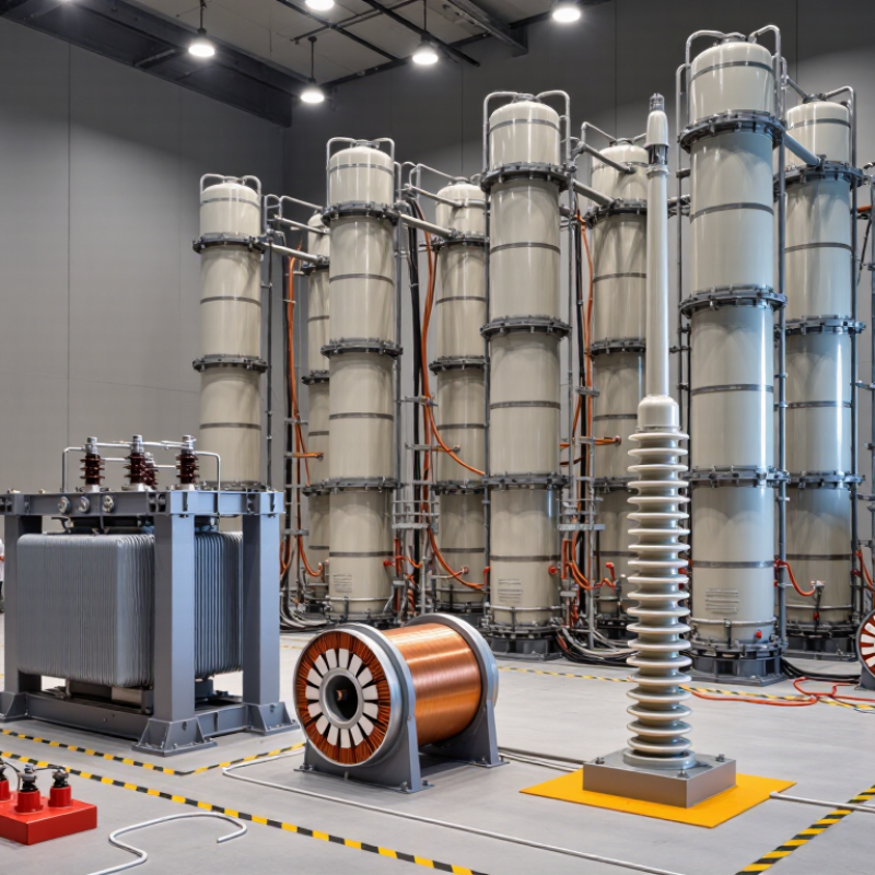
Safety, standards, and measurement accuracy should guide the purchase. In practical testing, inspect the enclosure, door interlock, emergency stop, discharge resistor, and visible grounding point. Remote operation is valuable when a generator releases a sharp acoustic impulse. The setup must make stored energy impossible to ignore. IEC 60060-1 defines requirements for high-voltage tests, including impulse characteristics and test conditions. A compliant-looking cabinet is not enough.
Ask whether the generator supports IEC 61083-1-compatible digital recording and traceable calibration. The National Institute of Standards and Technology, in Technical Note 1297, describes expanded uncertainty using coverage factor k=2, commonly representing about 95% confidence. That figure is useful, but not universal. Non-normal data and poor environmental control can make it misleading. I have seen clean waveforms become unstable after a probe cable warmed under repeated shots.
Accuracy depends on more than the stated voltage percentage. Check peak-voltage error, front-time measurement, time-to-half-value accuracy, sampling rate, bandwidth, and trigger stability. Request calibration records from an ISO/IEC 17025-accredited laboratory. Review uncertainty budgets, not only certificates. Temperature, humidity, grounding, and probe placement can change results. Small details matter. A generator may meet the standard while producing questionable measurements in your actual laboratory. Require a witnessed acceptance test using your load, fixtures, and normal operating range before approval.
Long-term testing needs a generator that behaves predictably after months of repeated pulses. Start by matching impulse waveform, peak voltage, energy, and repetition rate to your test plan. A unit rated for higher voltage is not automatically safer or better. Check rise time, decay time, load range, and measurement accuracy under real conditions. During evaluations, I prefer seeing complete pulse records, not polished specification sheets. Small details matter. Ask how calibration is performed, how often it is recommended, and whether certificates are traceable to recognized laboratories.
Reliability also depends on construction and maintenance access. Look for insulated enclosures, interlocked doors, emergency discharge circuits, and clear grounding points. The control system should record pulse count, faults, operator actions, and environmental conditions. These records can expose drift before it damages a testing program.
Cooling deserves attention too. A generator may run well for twenty minutes, then become unstable after several hours. Request endurance data at your intended duty cycle, temperature, and load. If testing only covers short bursts, keep asking why.
Service support often determines the real ownership cost. Confirm spare-part availability, response times, software support, and technician training. A clear troubleshooting guide can prevent unnecessary downtime. Test the generator with your actual fixture, cables, and sensors before purchase. Unexpected reflections may alter the waveform. This is where many evaluations become too optimistic. No selection is perfect; maintenance budgets, room space, and operator skill can change the decision. Leave room for those uncomfortable facts.
You are using an outdated browser. Things may not appear as intended. We recommend updating your browser to the latest version.
Close